Autoflight Practice
1. Automatic Flight Control Systems (AFCS): General Idea
An Automatic Flight Control System (AFCS) is designed to control the aircraft automatically while still behaving in a way that feels predictable and safe to the pilot.
At the heart of AFCS design is a fundamental trade-off between two opposing characteristics:
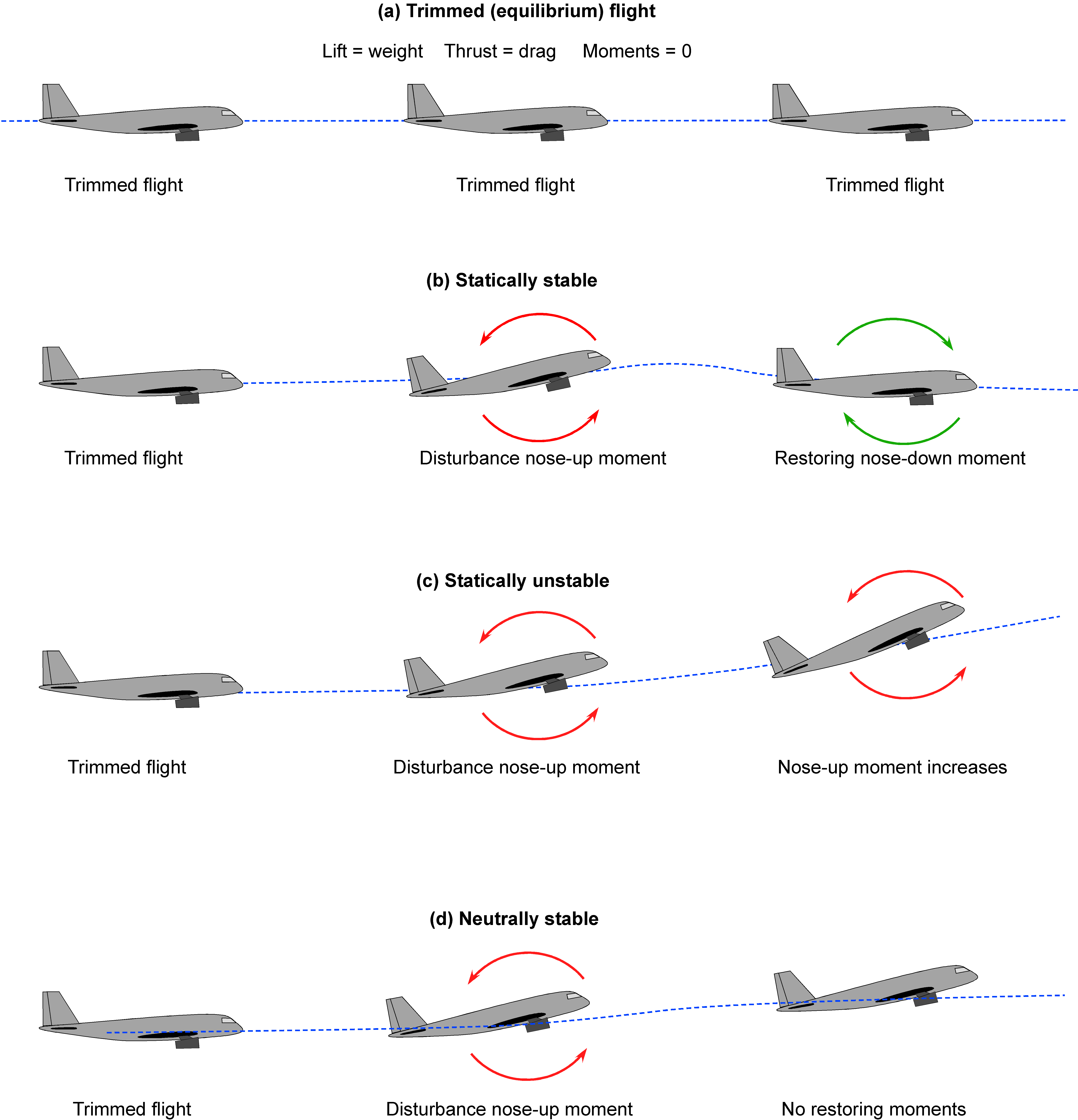
Stability
- The tendency of the aircraft to remain on a given flight path
- Minimises oscillations and sudden movements
- Provides a smooth, comfortable ride
Controllability
- How quickly and accurately the aircraft responds to control inputs
- Allows the system to track commands such as altitude, heading, or vertical speed
Because:
- High stability → slower response
- High responsiveness → reduced stability
…the AFCS must continuously manage this balance. This balance defines the man–machine interface of autoflight: the system must feel stable and capable of accurately following the desired flight path.
2. Stability vs Controllability and the Effect of Speed
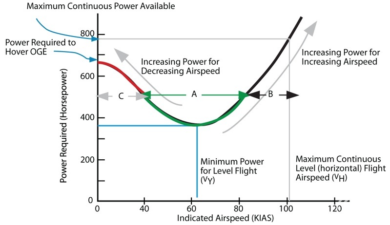
Aircraft operate over a very wide speed range, which strongly affects control behaviour:
Low speed
- Control surfaces are less effective
- Aircraft response is sluggish
High speed
- Control surfaces are very powerful
- Small deflections can cause large responses and structural loads
Variable Gain in AFCS Feedback Loops
To handle this, modern AFCS use feedback loops with variable gain.
Increased Gain
- Faster response to deviations
- Reduced stability margin
- Useful at low speed to improve control effectiveness
Decreased Gain
Increased stability
Slower, smoother responses
Useful at high speed to:
- Avoid overly sharp manoeuvres
- Protect the airframe from overstress
In practice, AFCS computers continuously adjust gain based on:
- Flight phase
- Aircraft configuration
- Density altitude
- Speed
The system also compensates for changes in longitudinal stability caused by:
- Flap extension
- Slat deployment
3. Control Laws
The rules governing how the autopilot commands the aircraft are known as control laws.
In AFCS, control laws define:
- Maximum control surface deflections
- How the system responds to deviations
- Pitch and roll limits the autopilot will not exceed
Control laws ensure that:
- The aircraft responds appropriately for its current speed
- Structural and aerodynamic limits are respected
- The system remains predictable and safe
The term control laws is also used in manual fly-by-wire systems (for example, Airbus aircraft). Although applied differently, the purpose is the same:
To provide correct control inputs for the current airspeed, configuration, mass, and centre of gravity.
4. Closed-Loop Control System Elements (AFCS)
According to the EASA learning objectives, an AFCS is a closed-loop control system.
It contains the following elements:
Input signal
- Desired state (e.g. selected altitude or heading)
Error detector
- Compares desired state with actual state
Signal processor
- Applies control laws and gain
Control element
- Actuator or servo driving the control surface
Feedback signal
- Aircraft response fed back to the error detector
This continuous loop allows the AFCS to:
- Detect deviations
- Correct them automatically
- Maintain the desired flight path


5. Key Points to Remember (Exam-Focused)
AFCS design is always a compromise between stability and controllability
Feedback loop gain is adjusted continuously:
- High gain at low speed → better control authority, less stability
- Low gain at high speed → more stability, structural protection
Control laws define:
- System response
- Control limits
- Pitch and roll boundaries
A closed-loop control system uses:
- Input
- Error detection
- Signal processing
- Actuator
- Feedback
1. Purpose of Autothrust
Autothrust (A/THR) or Autothrottle (A/T) is designed to automatically control engine thrust in order to maintain a selected flight parameter.
Its main purposes are to:
- Maintain speed or thrust as required by the active flight mode
- Reduce pilot workload, especially during high-workload phases and when hand-flying
- Provide consistent, predictable thrust management
Terminology differs by manufacturer:
- Boeing → Autothrottle (A/T)
- Airbus (and others) → Autothrust (A/THR)
Functionally, the systems achieve the same goal.
2. What Autothrust Controls
Autothrust can operate in two basic control philosophies, depending on which system (pitch or thrust) is controlling speed.
Thrust Mode
Autothrust sets and holds a fixed thrust level
Typical thrust references:
- TO/GA
- CLB
- MCT / CON
- IDLE
Used when the vertical mode controls speed
Examples
- LVL CHG
- VNAV SPD
- Airbus OP CLB / OP DES
Here:
- Pitch → controls speed
- Autothrust → controls thrust
Speed Mode
Autothrust varies thrust to maintain a selected speed
Speed target comes from:
- MCP
- FMC / FMGS
Used when the vertical mode controls flight path
Examples
- ALT HOLD
- V/S
- G/S
- VNAV PTH
Here:
- Pitch → controls flight path
- Autothrust → controls speed
Engine Limits and Protection
Regardless of mode:
Autothrust commands N1 (or EPR on some engines)
Commands are limited by:
- FMC-computed thrust limits
- Engine control logic (FADEC, PMC, ECU)
Engine computers always prevent exceedance of certified limits (“low-wins logic”)
3. Key Autothrust Modes (EASA-Relevant)
The following thrust modes are commonly examined:
TO/GA – Take-off and go-around thrust
THR CLB / THR MCT / N1 / EPR / THR HOLD
- Fixed thrust modes
- Used for climb or maximum continuous thrust
SPEED / MCP SPD
- Variable thrust to maintain speed
THR IDLE / RETARD / ARM
- Idle thrust for descent and landing
Landing
- Typically RETARD or THR IDLE during the flare (type-dependent)
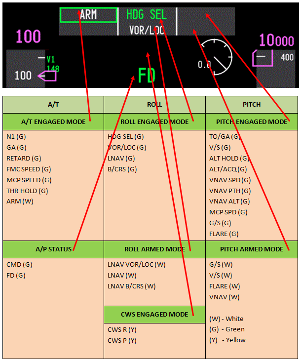
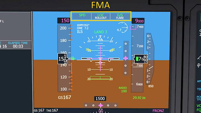
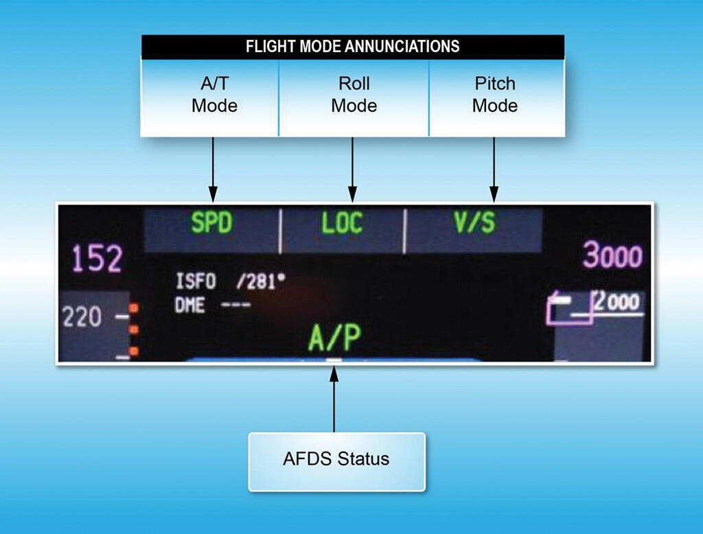
Mode Indications
- Pre-EFIS aircraft → Thrust Mode Annunciator (TMA)
- EFIS aircraft → Engine display + Flight Mode Annunciator (FMA)
➡️ The FMA is the primary reference for the active autothrust mode
4. Variants of Autothrust Systems
There are two main design philosophies.
Moving Thrust Levers (Boeing-style)
- Thrust levers are motorised
- Lever position always reflects commanded thrust
- Mode selection via MCP
- TOGA switches located on or under the thrust levers
- Pressing TOGA physically drives levers to the TOGA position
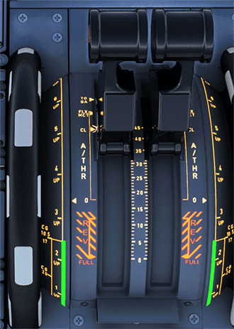
Fixed Thrust Levers (Airbus-style)
Thrust levers are not motorised
Levers placed in detents:
- TOGA
- FLEX/MCT
- CLB
Lever position itself determines thrust mode
No TOGA switches:
- TOGA is commanded by moving levers to the TOGA detent


5. N1 Thrust Mode Operation
N1 mode commands and maintains the N1 limit calculated by the FMC.
Thrust Limit Management
Active thrust limit is:
- Selected on the CDU N1 LIMIT / REF page
- Displayed above the N1 gauges
Typical limits:
- TO
- CLB
- CON / MCT
Example Sequence
Before take-off
- FMC computes take-off N1 (possibly reduced via assumed temperature)
- Pressing TOGA → A/T enters N1 mode and sets this value
After acceleration altitude
- Selecting N1 on MCP → active limit changes to CLB (e.g. ~89% N1)
After engine failure
- CON/MCT selected to provide maximum continuous thrust for engine-out climb
Even if a higher value is selected:
- FADEC / PMC logic prevents engine exceedance
6. Engine Control Unit / PMC (Non-FADEC Systems)
On older engines:
- Fuel flow is primarily controlled by a hydro-mechanical ECU
- A Power Management Controller (PMC) may be added
PMC Functions
- Fine-tunes fuel flow electronically
- Maintains accurate N1
- Provides limited exceedance protection
- Allows automatic climb thrust without lever movement
Failure Case
If PMC fails:
- ECU reverts to manual, lever-based control
- No automatic thrust limit protection
- Pilot must manually avoid exceedances
7. Autopilot–Autothrust Interaction (Critical Concept)
Autopilot and autothrust must always be interpreted together.
Vertical pitch mode determines:
- Whether pitch controls speed or flight path
Autothrust mode complements this:
- Thrust mode or speed mode
Key Rule to Remember
One system controls speed, the other controls flight path — never both at the same time
Understanding this interaction is essential for:
- Mode awareness
- Correct aircraft energy management
- Avoiding unexpected pitch or thrust changes
8. Key Exam Takeaways
Autothrust automatically controls engine thrust to reduce workload
Two operating philosophies:
- Thrust mode → fixed thrust
- Speed mode → variable thrust
Active mode is always confirmed on the FMA
Two design philosophies:
- Moving levers (Boeing-style)
- Fixed detent levers (Airbus-style)
N1/EPR limits are calculated by the FMC and protected by engine logic
Autopilot pitch mode and autothrust mode must always be analysed together